Tuesday 22 April 2014

Lesson 11: Multiple animations (part 3)

In the previous lesson, we looked at a sequential animation where a pair of doors opened, followed by a drawbar sliding across. But the animation only worked in one direction because the opening doors were linked to the onClick handler so they always began first, even when reversing the animation. Now we shall look at how to make the animation sequence work correctly in both directions in a copy of the last version (now called "DC7").

The principle then is to have one animation, the Timeline, and link each door and the drawbar to this attribute. Let's start by examining the values we are working with.

Door 1 (LeftAngle) begins at -90 when open and ends at 0 when closed
Door 2 (RightAngle) begins at -90 when open and ends at -180 when closed
The Drawbar (BarPosition) begins at -210 when drawn back and ends at -5 when closed
The Timeline will go from 0 to 100 in 1.1 seconds.

As a chart, this is:

Time 0 seconds 0.5 seconds 0.6 seconds 1.1 seconds
Timeline 0 45% 55% 100%
LeftAngle -90 0 0 0
RightAngle -90 -180 -180 -180
BarPosition -210 -210 -210 -5
Process Start doors End doors Starts bar End bar

Notes: the % in the Timeline isn't included when we enter actual values, it's just there to show that the Timeline is like a counter going from 0 to 100% (completed). The Process when reversed, would be "End Doors - Start Doors - End Drawbar - Start Drawbar".

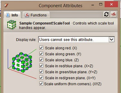
The first thing to do is to remove all the formulas and functions from the main "DC7" attributes (but leave the formulas in the subcomponents linking the Doors' RotZ to LeftAngle and RightAngle, and the Drawbar X position to BarPosition). Your Components Attributes window should look like this:

Now we add the single animation to the onClick attribute:

ANIMATECUSTOM("Timeline",1.1,0,0,0,100)

This is almost the same as the one we used in the previous lesson except that Timeline is now going from 0 (%) to 100 (%) and the easing is zero-zero since I want no change in acceleration. Clicking on the component now seems to have no effect but, if you make the Timeline visible, you can see it changing from 0 to 100 and back on each click.

(If you have forgotten how to make an attribute visible, click on the Details button on the right of the Timeline which looks like a menu combined with an arrow (see image below). Change "Display Rule" to "Users can see this attribute" and Apply. Now, if you have the Component Options window open when you click, you can see the value of the Timeline changing.)

The Details button, used to make the Timeline attribute visible


The formulas

Now for the formulas. If we start with the left door, we see that when Timeline is zero, LeftAngle must equal -90 and, when Timeline is 45, it must equal 0. If we add 90 first to get rid of the negative numbers (which can be confusing) we find that


0 Timeline = 0 LeftAngle
45 Timeline = 90 LeftAngle

and the formula is therefore:

LeftAngle = (Timeline * 2) - 90

(The brackets aren't necessary because of the rules of algebra but they make things clearer.)

When working out a formula, remember to add some intermediate angles in the calculation to check. In this case. 22.5 would be halfway along the Timeline and the LeftAngle would be -45 which, when I check the calculation, works out correctly. This is where the spreadsheet comes in useful.

The formula that we need to enter in the LeftAngle then is:

=IF(Timeline>45,0,Timeline*2-90)

Meaning: if the Timeline is greater than 45, set it to zero (closed), else animate it.
 Enter this, click on the component and you should see the left door open and close.

Note: the fact that the Timeline value is exactly half the LeftAngle is coincidence. It makes it a bit easier but isn't important.

For the second door, we need:

0 Timeline = -90 RightAngle
45 Timeline = -180 RightAngle

A formula I worked out for this is:

RightAngle = 0 - ( 90 + ( Timeline * 2 ) )

 thus

=IF( Timeline>45, -180, 0-(90+(Timeline*2)) )

So now, clicking the model opens both Doors.

Note that, after the Doors open, the animation runs on for 0.6 seconds with nothing apparently happening so don't click again too soon after the first click. Allow the animation time to finish.

Finally the Drawbar where we need:

55 Timeline = -210 BarPosition
100 Timeline = -5 BarPosition

Thanks to Excel, I find that the formula is:

BarPosition = (4.5556 * Timeline) - 460.5

so the formula for BarPosition is:

=IF(Timeline<55,-210,4.5556*Timeline-460.5)

Now, click on the component and two animations work together, both opening and closing.
The final settings:

Creating timelines and linking multiple animations is tricky, involving caeful maths and logical thinking, but the results can be very pleasing.

The final model is available on 3D Warehouse at https://3dwarehouse.sketchup.com/model.html?id=u9644e7be-7be5-4764-a2e6-785d96c41259

Monday 21 April 2014

Lesson 10: Multiple animations (part 2)

Sequential animations

While simultaneous animations are easily produced by placing them together in an attribute, the sequential animation is more complicated. Basically one animation, often an abstract custom attribute, is begun as normal, usually by an onClick formula, while the others are controlled by accessing the value of the first.

As an example, let's elaborate the opening doors we created in Lesson 9. In castles, the main doors were often secured by sliding a wooden beam across when closed so we shall add this to the twin doors. Our animation will consist of the two doors closing and then, once the doors are closed, the drawbar will slide across.

First duplicate the two door component we created in "DC5" and rename it as "DC6". Within the component, create a rectangle named "Drawbar" and position it in the final, closed position as below. Add the X attribute to the Drawbar and make a note of its value.

 Next we need to move the elements to their 'start' postion, so change the Doors' "RotZ" values so they are both open (remembering that we are changing the custom attributes "LeftAngle" and "RightAngle", not the RotZ directly). Then change the Drawbar's X position so that it is drawn back as shown below.


The first animation is straightforward, keeping the existing "onClick" to rotate the doors. The second animation involves the Drawbar sliding across by changing the object's X position. But we don't want this to happen until the doors are closed so how do we accomplish this? One technique is to create a custom attribute which will have a timeline and the animations are based on this, determining their values from this attribute. In this case, because the doors start at the same time as we click it, we can leave them as they are, but the moving of the Drawbar will need to controlled by this.

Before we create anything though, we need to get out a pen and paper (or spreadsheet) and work out some timings. The doors use the Animate function which occurs over half a second so let's say the Drawbar animation will start at 0.6 seconds (to allow a more realistic slight pause between the actions). The Drawbar animation can also take half a second so the total length of the full animation is 0.5 + 0.1 + 0.5 = 1.1 seconds.

In my model, the X position of the Drawbar is -210 when withdrawn and -5 when closed so, putting these together in a table:

Time 0 secs 0.6 secs 1.1 secs
Drawbar X -210 -210 -5
Timeline -456 -210 -5

Now comes the complicated part of working out a formula. I worked out the Timeline figures so that the Drawbar X position matches the Timeline but, obviously we don't want the Drawbar to move until the Timeline reaches -210 so we need to add an IF formula which says (in English):

If Timeline is less than -210, Drawbar position is -210, else Drawbar position is equal to Timeline.

As a SketchUp formula, it is (notice no quote marks around the attribute names:

=IF(Timeline<-210,-210,Timeline)

Finally we simply link the Drawbar position to the Timeline.

The final formulas are shown below:

You may have noticed the CUSTOMANIMATION that controls the Timeline animation. Because we want an odd number, 1.1 seconds, we can't use the standard ANIMATION types so have to use a CUSTOMANIMATION. The parameters for this formula are, compared to the normal ANIMATION:

ANIMATION(attribute, state1, state2 ...)

CUSTOMANIMATION(attribute, time, easein, easeout, state1, state2 ...)

The only thing that might be puzzling is the easein and easeout. These determine the acceleration of the animation with 0 being the fastest and 100 being slowest. The default easein and easeout for an animation is 0 and 100 which means the animation starts fast and slows down, rather like a ball being thrown in the air. Values of 100 and 0 would mean it starts slowly and speeds up (like a rocket taking off).

The details we enter are:

ANIMATECUSTOM("Timeline",1.1,0,100,0,-456,-5,-456)

which means the Timeline value changes over 1.1 seconds, starting quickly and slowing down, going from -456 to -5 on the first click, then back to -456 on the second click.
If you click on the component now, you should see doors open and then, after a pause, the drawbar slide across.

The reverse  animation doesn't work properly with the doors opening before the Drawbar has slid back but, to have the animation working both ways requires a more complicated arrangement. For this to work, you would have to link the animations of both the Drawbar and the two doors to the position of the Timeline which is much more complicated. Maybe you can think about how to achieve this. I shall show my method in the next lesson.


The completed component is available on 3D Warehouse at https://3dwarehouse.sketchup.com/model.html?id=ud59967fd-643b-4621-aeb5-d1cbbbc9fb19

Monday 14 April 2014

Lesson 9: Multiple animations (part 1)

Up to now, all the animations we have created have been simple, one-step animations: the window swings open or close. But some of the more impressive effects are multiple animations and there are two sorts: simultaneous and sequential.

Simultaneous animations

Animations where two or more changes occur at the same time are easy to create. All that is necessary is to add the different effects in the same onClick (or other) area, separated by semicolons, e.g.

ANIMATE("X",0,50); ANIMATE("Y",0,100)

The order is irrelevant as they start together. (They may end at different times depending on which type of animation you use.)

As an example, we shall create a pair of double doors which open simultaneously. So create a door with a cutaway corner (see image below) and make it into a component. Duplicate it and flip the copy along the red axis so that the axes are on the outside (this is where the cutaway shape comes in useful). Then make the two doors into a component ("DC5"). It should look something like this:

 
To open the doors, we add an onClick to the DC5 component to animate them. How do you know which of the two sub-components is which? Well, if you add the X attribute to both doors, you will see that one has a X position of 0 (the left) while the other has a value twice the width of the door. You can also look at the RotX of both which will show 0 and -180.

The problem with the model at the moment is that we have used two copies of the door component; consequently  they both have the same name. If we rename one, they both get renamed. If we animate the RotX, SketchUp can get confused as to which we are referring to. We could have used groups which would be separate but, because the doors are identical, it is better to use components.

To get around the problem, we can create two custom attributes in the top level "DC5" to hold the angles for both doors: LeftAngle and RightAngle. We enter 0 into the first and -180 into the second, then link the RotZ of each door to its appropriate value.

=DC5!LeftAngle
and

=DC5!RightAngle

If we now enter different values into LeftAngle and RightAngle, we should see the doors adjust their angle.

Finally, we enter the two animations into the onClick box of "DC5", separated by a semicolon. The first changes LeftAngle, the second changes RightAngle. If we click the doors with the Interact tool, the doors should open and close together.

If your component isn't working, check it against these formulas:


The model, DC5, is available on 3D Warehouse at
https://3dwarehouse.sketchup.com/model.html?id=u2ba92957-10fd-48bf-b004-9d9d4219e20e

In the next lesson, we will look at how to create sequential animations where they do not occur at the same time.

Monday 7 April 2014

Lesson 8: Limiting the Scale tool, and other attributes

This week, a break from creating dynamic components with a look at the other attributes in the Component Attributes window. We have already seen many of them and most are self-explanatory but let's look at some of the others.

The group titled "Component Info" are all to do with what appears in the Component Options window. The position of the various attributes are shown below. You can also see a piece of italic text in the description and this is to show that you can use HTML codes in any of these areas. Only certain codes are available but they can make your text look more interesting and you can add links to your webpage, for instance.


Available HTML codes
    <a> anchor
    <b> bold
    <i> italic
    <u> underline
    <strong> bold
    <em> italic
    <p> paragraph
    <br> line break
    <ol> ordered list
    <ul> unordered lis
    <li> list item
    <font> font size, colour, etc

The "Form Design" group have similar uses. "ImageURL" allows you to replace the default thumbnail with your own image. The "DialogWidth" and "DialogHeight" determine the size of the Component Options window. (If you are working on a large screen, don't make the "DialogHeight" too large – remember other people will have smaller windows.)

The "Hidden" attribute simply hides or shows a subcomponent. This could be useful where, for example, you have a vehicle with different designs – a lorry that could be flat bed or enclosed. I also used it in a restaurant dining table/ chair set so that you could have variable options – one chair, two chairs opposite, two chairs side-by-side.

The final attribute "ScaleTool" is often used with dynamic components to disable or limit the use of the Scale tool with your component. As an example, imagine you have created a ladder that adds extra rungs as you lengthen it (increase the LenX). It would be all right for the Scale tool to be used to make the ladder longer but not to change the other dimensions (LenY or LenZ). That would distort the rungs and supports. With the ScaleTool attribute, you can disable some or all of the ways the Scale tool can be used.

To do so, double-click the "ScaleTool" attribute or click the menu-arrow icon to the right. The screen below appears.


As you click on the checkboxes, you can see the handles appear and disappear meaning that the Scale tool cannot be used in that way. The easiest way to understand is to deselect some of the checkboxes, click apply, and then try to scale your component with the Scale tool. The setting below shows how the checkbox combination is mirrored when using the Scale tool.

Tuesday 1 April 2014

Lesson 7: Dynamic copies

Previous lessons have looked at simple dynamics such as changing a single attribute but this lesson will tackle something more complicated and which can sometimes take a while to get your head around – dynamic copies.
As an example, imagine a ladder with 10 rungs spaced 50 cm apart. If you double the length of the ladder, you don't want 10 rungs spaced a metre apart, you want 20 rungs spaced 50 cm apart. Similar needs come with sets of stairs, fences, furniture with multiple drawers.

For this tutorial, we shall again keep things simple so you can understand the principles without getting confused by details. Start by creating a block 100 x 50 x 200 on each side, group it and name it "Wall". Then create a step 50 x 10 x 30, make it a component (because it will be repeated, unlike the wall), and name it "Step". Position the step at the bottom edge of the block (see below), then select both and make it in to a component "DC4".


 Notice that we have only made one rung. All the others will be handled and duplicated automatically by formulas but, before we do that, we shall add a couple of custom attributes. Under the DC4 component, add two custom attributes: "TotalHeight" and "Spacing". The first determines the total height of the component so enter "50" for the moment. Then, under the Wall element, add the attribute LenZ and enter into its box the formula:

=DC4!totalHeight

The height of the Wall is now linked to TotalHeight so we can change the height of the subcomponent Wall from the main DC4 component. The Spacing attribute determines how far apart the steps are so enter 50 at the moment (so we have one step per 50 cm of wall height).

If we now enter 100 into TotalHeight, we should see that the wall gets higher but nothing else happens. We need to handle the duplication of the steps to allow for the extra height and this is determined by the attribute called "Copies" (under OnClick in the popup menu). So add the Copies attribute to the Step element (since we are making copies of the Step and enter the formula:

=DC4!totalHeight/DC4!Spacing

This means that the height of the wall is divided by Spacing to determine the number  of total steps. If you try different values in TotalHeight, you should see the value in Copies change:

TotalHeight Formula Copies
50 50/50 = 1
100 100/50 = 2
150 150/50 = 3

So the number of steps is increasing with the height of the Wall. Wait, you protest, I can only see one Step! Well there really are the same number of Steps to match the Copies value but they are all in the same location as the original Step so you can't see them. What we need to do now is change the Y and Z positions of the copies of the Step so that they are positioned separately. This is handled by a new, read-only attribute which is not normally visible called COPY. This holds the number of each copy so the original Step is numbered 0, the next 1, then 2, and so on. If you view the X, Y and Z positions of the Step, you see that it shows X=100, Y=0 and Z=0. If we start with the vertical position of each Step, we already have the Spacing so we simply set the Z position to:

=DC4!Spacing*COPY

The results would be:

COPY No. Formula Z Position
0 50*0 = 0
1 50*1 = 50
2 50*2 = 100
etc.

After entering this formula, you should see the steps suddenly appear next to the wall.


 You can change the horizontal position as well by adding the same formula to the Y position. Now, as you change the TotalHeight, you will see Steps magically appear or disappear.
  
TIP if you double-click and open the component after these copies have been made and select one of the them, you will see the COPY number in the attributes (below)


If your component isn't working, here are the settings below:
Obviously the positioning isn't quite right and here comes the mathematical bit. You need to adjust the formulas to space things correctly, maybe adding on an offset or allowing for the thickness of the step. One of the best ways to go about this is a sort of reverse engineering – draw the final component on paper, working out what the positions of each step would be and work out a formula which would produce that. A spreadsheet comes in very useful here.
Sketch diagram of the finished dimensions

The final formulas which space the Steps correctly are:


Y position = (200-30)/Copies*Copy
Z position = (DC4!totalHeight-10)/Copies*Copy

As before, the component, DC4, is available on 3D Warehouse at

https://3dwarehouse.sketchup.com/model.html?id=udd41c4eb-9a36-43ea-81fa-c49421426634

Monday 24 March 2014

Lesson 6: Changing materials, and adding user selection menus

If you've been following the previous lessons, you should be comfortable with simple attribute changes (rotating a window), the onClick behaviour and animations. Now we'll look at another common dynamic action and the use of user choices through menus.

If you have downloaded the SketchUp example "Sang", you will see how you are able to change the colour (strictly speaking "material") of various features by clicking and that is what this lesson will teach, again by using a simple model so you can concentrate on the technique.

To create the dynamic component, create two cubes. On one of them, draw a circle and fill it with any material). Group it and call it "Sub1". Then create another cube, group it and call it "Sub2". Finally select both and make them into a component called "DC3" as shown below. Note that they should all be in the default material apart from the filled circle.


Next you need to add the various materials that you are going to switch to to the model. We need to create a set of swatches which will be kept within the component and hidden. If you do not do this, your user could remove the alternate materials if they purge spare materials from the model. By creating swatches, the materials cannot be removed by purging.

Go into the component (so that the swatches become part of it) and create four rectangles. Then pick the four materials or colours that you wish to use and paint each rectangle with each one, as shown below. (An alternate would be to create a cube and paint each face in a different material). You do not need to group or componentise (is that a word?) these swatches as they are going to be hidden and not used in formulas.


TIP If you use the material names that come with SketchUp, there is a danger that someone could edit that material and therefore change the appearance of your component. If you wish to make sure that your material doesn't change accidentally, edit the name to something unique like "DCcarBlue".


Whether you use the default material names or rename them, make a note of the exact name of each material as you will have to enter these in your formula.

The next step is to move the swatches into the body of the component and hide them. We need to move them inside because, even when hidden, they affect the outer size of the component. So move the swatches into the body of your component, making them smaller if necessary. Then hide them. (The illustration below shows them inside the body which has one face temporarily hidden.) It can be a tricky procedure getting them inside; you may need to switch views or use the X-ray mode to do so.


Now select the component and open the Component Attributes window where you should have "DC3" with the subcomponents "Sub1" and "Sub2". In Sub1, (the one with the coloured circle) add the attribute "onClick". You may also want to add the attribute "material" although it's not strictly necessary. Select the SET function from the Functions pop-up window menu and add it to the onClick attribute. We now need to add the familiar SET as before but with these settings:

SET("Material","mat1","mat2","mat3","mat4")

where "mat1", "mat2", etc. are replaced with the names of the materials you used in the swatches (they must match exactly apart from case). I had renamed the materials in my model so I entered:

SET("Material","DCred","DCyellow","DCgreen","DCblue")

Note that the materials must be enclosed in quote marks because they are names rather than numbers such as RotZ, LenX, etc.

Now click on the model with the Interact tool and you should see the materials change. A few things to note:
  • Only areas set to default material change, not those with materials already set (such as the circle)
  • Because we added the onClick to group "Sub1", it doesn't affect the default material of "Sub2". If we had added the onClick to the whole component ("DC3"), it would have changed both groups.
  • The Material attribute shows the present material name (but not in quotes).
TIP There is no point changing SET to ANIMATE in this situation because there is no "inbetween" one material and another so SketchUp cannot gradually change them unlike an angle or a dimension.

User selection menus

So far so good. But what if there were a dozen materials in the swatches? You wouldn't want to keep clicking to get to the material you wanted. It would be far easier to pick the choice from a menu, and this is easily added with one qualification. User menus can only be added to the top component, not a subcomponent, so we have to add a custom attribute to "DC3" and the material for "Sub1" will be linked to this.

First, create a custom attribute for "DC3" and call it "SubMaterial" (we cannot call it "Material" since that name already exists. User selection menus can be added to any attribute and are accessed by clicking the arrow like symbol that appears on the right of the attribute box (see below).

The window switches to another screen which initially shows "Display rule: Users cannot see this attribute". This menu has three other options:
  • Users can see this attribute (they can see what the attribute is but not change it)
  • Users can edit as a textbox (they can enter their own numbers or letters)
  • Users can select from a list (they have a choice of selection)
Select this third option:

"Display label" is the caption for the user menu: in this case I change it to "Colour", while the boxes below represent the menu values, "List option" is what the user sees in the menu, "Value" is what SketchUp enters into the formula. So click where it says "Add option" and enter a description of the first material. Where it says "Enter value", enter the name of the material as we typed into the onClick>SET formula. In my case:

LIST OPTION VALUE
Red DCred
Yellow DCyellow
Green DCgreen
Blue DCblue


and click "Apply" (note there are no quotes around either column).


Now, when you open "Component Options", you should see a menu named "Colour" where we can select a colour (and click Apply). Of course, it doesn't work at the moment because we haven't linked the Sub1 material to the custom attribute. So enter this formula in the Material attribute of Sub1.

=Parent!SubMaterial

What's that? Shouldn't it be "DC1!SubMaterial"? Well it could be but this is a little tip I thought I'd share. If you use "Parent" in any subcomponent, it always refer to the component or group which contains it – useful if you have a set of formula snippets you can use in any model without changing the names. (Note there is no equivalent "Child" term since a parent can have many children but a child can have only one parent (in the SketchUp world, at least).

So now, Sub1 material takes its value from the SubMaterial attribute which we change with the menu. Try it out. The settings are shown below in case you have any problems.
As before, DC3 has been uploaded to the 3D Warehouse with this link:

https://3dwarehouse.sketchup.com/model.html?id=ueae2f868-62b2-4d79-a810-539089877a60


Monday 17 March 2014

Lesson 5: Custom attributes and axes

First of all in this tutorial, an interesting thing you may encounter in your DCs.

If you have followed the last lesson, you should have a simple dynamic component called "DC1". (If not, go back to the lesson to create it or download it from 3D Warehouse.) Now go to the components window and make several duplicates of the wall/window. Click to open one of the copy's window. You should see all of the windows in each copy open in unison. This is not usually a good thing – if you have several doors in a building, you don't want them all to open at the same time.


I'm not sure why this happens, not being a SketchUp developer, but I know how to fix it: create custom attributes.

What are custom attributes?

As their name suggests, these are attributes which you define yourself. You can give them any name (as long as they start with a letter, have no spaces and are not the same as existing attributes) and you can give them any values, formulas and functions. On their own, because they don't refer to anything in your component, they do nothing but when linked to other attributes, they become very powerful.

Why would you create a custom attribute? Well, they might be used to define something which has no existing attribute, such as the spacing of rungs in a ladder, but they might also be used to represent existing attributes. What would be the point of that? Well there are several reasons:
  • To give a more logical name to an attribute: "Height" might be more obvious to you than "LenZ"
  • To shorten the  name of a long attribute for use in formulas, eg. "Battlements!material" to "BMcolour" (If you're puzzled by the exclamation mark, I shall explain this below).
  • To refer to a deeply nested subcomponent. (If you have a subcomponent within a subcomponent within the top component, you can only refer directly to the attributes of the next level down.)
  • To differentiate identical subcomponents. (If you have the same component repeated in a DC, they will all have the same name.)
  • To allow users to choose attributes from a menu or enter values.

The exclamation mark

If you have used spreadsheets, you may have come across the exclamation mark in formulas when referring to different sheets. They work in a similar way in SketchUp.

Since every subcomponent, as well as the main component, has their own set of attributes, you need some way to refer to, for example, the window's RotZ instead of the wall's RotZ. So you enter the component's name first, followed by the attribute name, separated by the !. You can think of it as the equivalent of "apostrophe-s-space" so "Window!RotZ" means "Window's Rotz". If the formula is referring to its own subcomponent's attribute, in the sense that our onClick was in the "window" and referring to the "window", the first part and the ! are not necessary.

TIP If you click on the attribute name when entering attributes in formulas, SketchUp automatically adds the prefix and ! if necessary.

Amending DC1

To introduce you to custom attributes, we will add one to our DC1 model which also gets rid of the "linked" windows problem. Open the DC1 file, click on the dynamic component and open the attributes window. In the top component (named "DC1"), click where it says "Add attribute". The attribute menu pops up but you'll also notice the "Add attribute" wording changes to "Enter name". Ignore the menu of attributes and just type the name of the custom attributes in this box and press return. (I shall name it "rotation".)

This attribute is going to hold the rotation of the window, that is, the window's RotZ value. So click in rotation's field and enter the value zero. Now we have to link the RotZ attribute so that it is using the rotation value. Delete the value from RotZ and enter:

=DC1!rotation

Finally we have to amend the onClick so that it is changing rotation instead of RotZ so change it to this:

SET("DC1!rotation",-45,-90,0)

Now create multiple copies of our new component and click on the windows. They should all open independently. (I'm guessing that custom attributes are stored separately for each copy so they can have have different settings. Maybe a SketchUp expert can confirm this.)


If your component doesn't work, check your values with the screenshot below.

If it still doesn't work, I have uploaded to 3D Warehouse (named "DC2"). The link is:
https://3dwarehouse.sketchup.com/model.html?id=uafd2d6fb-4d03-4f14-9cbc-cc9648981d1c

A look as axes

(That is, the plural of axis, not the chopping tool)

When creating the window in the last lesson, you might have wondered how to have the window rotate differently, such as with a horizontal axis, or from the centre, like a revolving door. It is simple to achieve this, and you just have to understand about the axes.

In any SketchUp model, you will be aware of the document's axis, the red, green and blue lines that appear in the middle of the screen and control the snapping when drawing. But you may not be aware that every group and component has its own axis which is independent of the document's. To see this, create a simple cube and group it. Then rotate the cube. When you double-click to open and edit the group, you should see that it has its own red, green and blue lines which now point in different directions from the document's.

Many of the attributes of a dynamic component are related to this axis: the X, Y and X positions are measured from the crossing of this axis, the rotations are around it and the lengths are measured from it (if you make something smaller via attributes, the axis end stays fixed and the other end gets shorter). So, if you need to rotate from a different point, you just have to open the group/component and redraw the axis. (To find out how to move axes, check the SketchUp documentation.)

You can practise by repositioning the axis of your cube and entering different positions and rotations in the attribute window.

Therefore, to change how the window rotates, just go into the window subcomponent of the DC1 model and move the axis. To get the window to rotate like a revolving door, move it to the centre; to get it to rotate from the top (like a letterbox flap), move the axis to the top and move the formula to the RotX attribute (see below).

Top axis window


Centre axis window